Adiabatic capillary tube (a) block diagram (b) P-h diagram Figure
Par un écrivain mystérieux
Last updated 06 juillet 2024

Download scientific diagram | Adiabatic capillary tube (a) block diagram (b) P-h diagram Figure 1.1a shows the vapour compression system employing the adiabatic capillary tube as an expansion device. As the flow through the capillary tube is adiabatic, the enthalpy of in adiabatic capillary tube, the refrigerant expands from high pressure side to low pressure side with no heat exchange with the surroundings. The refrigerant often enters the capillary in a sub cooled liquid state [1]. As the pressure of refrigerant falls below the saturation pressure a fraction of liquid refrigerant flashes into vapor. 1.2 Diabatic Straight Capillary Tube from publication: CFD Parametric Investigation for Two Phase Flow of Refrigerant 134a In an Adiabatic Capillary tube | Capillary tubes are widely used as refrigerant flow control device in a small refrigeration systems. Since the flow behavior inside a capillary tube is complex, several physical models are necessary to predict the characteristics of refrigerant flow in the capillary tube. A | Refrigeration, Two Phase Flow and Condensation | ResearchGate, the professional network for scientists.

Probing Acid-Induced Compaction of Denatured Proteins by High-Pressure Electrospray Mass Spectrometry
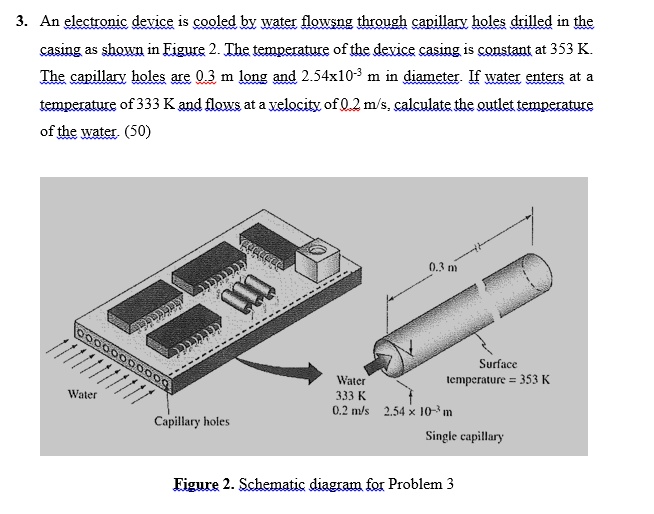
SOLVED: An electronic device is cooled by water flowing through capillary holes drilled in the casing as shown in Figure 2. The temperature of the device casing is constant at 353 K.

Figure 1 from Numerical and Experimental Studies on Adiabatic and Nonadiabatic Capillary Tubes with HFC-134 a

Vapor/Compression Refrigeration
Energies, Free Full-Text

Pool Boiling Heat Transfer on a Micro‐Structured Copper Oxide Surface with Varying Wettability - Sen - 2022 - Chemical Engineering & Technology - Wiley Online Library

Adiabatic capillary tube showing different flow regions and

PERFORMANCE ANALYSIS OF VAPOR COMPRESSION REFRIGERATION SYSTEM USING DIFFERENT DIAMETER CAPILLARY TUBE AND R12 AS REFRIGERANT
Enhanced Evaporation Strength through Fast Water Permeation in Graphene-Oxide Deposition
What is the h-s diagram for vapour compression refrigeration cycle? - Quora
Recommandé pour vous
 RÉFRIGÉRANT À AIR POUR TUBE À ESSAIS14 Jul 2023
 Zerone tube de réfrigérant Tuyau de réfrigérant de remplissage de14 Jul 2023
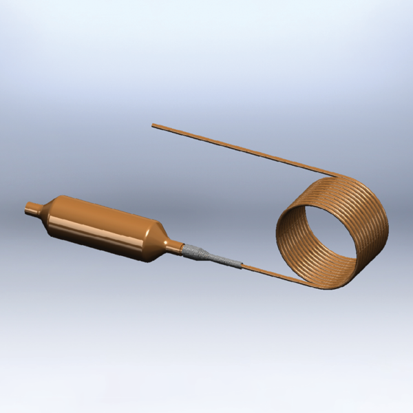 Capillary Assemblies - Strainer-Drier - Refrigeration Research14 Jul 2023
 Refrigerant Shell and Tube Condenser. HMAT and HAMM Series14 Jul 2023
 Refrigerant Dip Tube 48 Polymar14 Jul 2023
 How a Pulse Tube Refrigerator Works - Cryogenic Refrigeration14 Jul 2023
 Les tubes cuivre utilisés en climatisation !14 Jul 2023
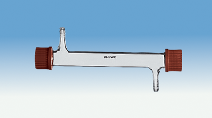 Tube réfrigérant, GL 25/814 Jul 2023
 refroidisseur de tube réfrigérant carré de 10 cm14 Jul 2023
 SYSTERM Conduite de réfrigérant pour climatisation split, tube en cuivre isolé prêt à l'emploi 1/4 + 1/2, les tubes préisolés pour gaz de14 Jul 2023
Tu pourrais aussi aimer
 Agenda 2024 Planner Notebook and Notepad Bullet Calendar Diary Stationery Journal Organizer Sketchbook A5/A4 Daily Note Book 365 - AliExpress14 Jul 2023
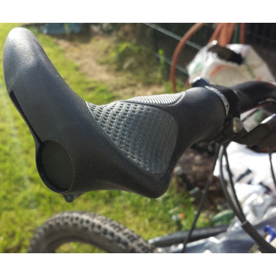 Paire de poignées de velo confortables à cornes14 Jul 2023
 ÉCLAIRAGE PLAQUE D´IMMATRICULATION POUR OPEL ASTRA G 98-0414 Jul 2023
 Manucure/Pédicure - Cool Maker Go Glam Nail U-nique Nail Salon - Spin Master14 Jul 2023
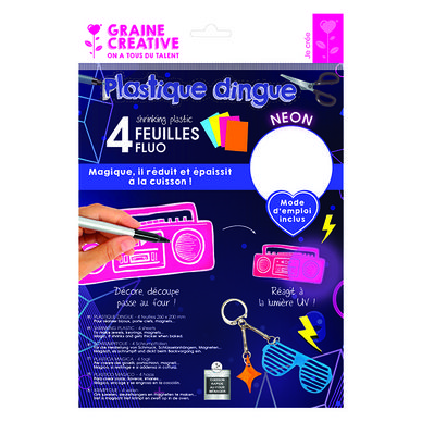 Plastique dingue Fluo 4 feuilles 20 x 26 cm Graine Créative chez Rougier & Plé14 Jul 2023
 Marvel's Star Wars: The Mandalorian – Season 2 #8 — Exclusive14 Jul 2023
 Ressort (spirale) f. tirer le démarreur14 Jul 2023
 Samsung BN59-01358B Télécommande d'origine Smart TV (Réf#F-640)14 Jul 2023
- Les Élevages Westmount - Pour obtenir une bonne viande, tout est14 Jul 2023
 Cuir éco, cuir artificiel Tapis coffre pour Seat Leon III break14 Jul 2023
